A Business Process Diagram (BPD), using Business Process Model and Notation (BPMN), is a graphical representation of a process; used for communication, documentation, visual analysis, and implementation. A BPMN diagram depicts the end-to-end flow of a transaction through a business process, and its behavior can be simulated.
Creating and Importing BPNM Diagrams
BPMN diagrams can be created under the top folder in the repository tree or any document (non-enterprise-object) folder.
See Diagram (web-authored) for information on
Objects in BPMN Diagrams
BPMN defines four types of objects for drawing:
-
Pools and Lanes (Swimlanes® or Departments): Each top-level swimlane (department) represents a BPMN Pool, and each child department is called a Lane. They contain other objects, such as flow, connection, and artifact objects.
-
Flow Objects: These are shapes that represent behavior of steps in the process; there are three types:
-
Events: Something happens; such as a start or end of the flow.

-
Activities: Work is performed, or a reference to a subprocess is made.

-
Gateways: Control the flow of a token (transaction) through the process.

-
-
Connection Objects: These are the connection lines between flow objects and swimlanes. There are three types of connections:
-
Sequence Flow: Tokens, or transactions, move between flow objects (shapes). Sequence Flow is represented by a solid line with an arrowhead.

-
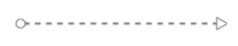
Message Flow: Messages move information between pools (floating departments). Message Flow is represented by a long-dash line with an arrowhead.
-
Association: Attaches an artifact to the object it annotates. Associations are represented by a short-dash line without an arrowhead.

-
-
Artifacts: These are notes or annotations to the diagram. They may be textual or graphical.
The BPMN Diagram tab provides the following menu of BPMN object sets
-
Core – The most used objects.
-
All – All available objects.
-
Containers – All container objects.
-
Tasks: All – All task objects.
-
Tasks: Standard – Commonly-used task objects.
-
Tasks: Extended – Additional task objects.
-
Gateways – All gateway objects.
-
Events: All – All event objects.
-
Events: Top Level – Primary process event objects.
-
Events: Boundary – Receive and catch objects.
-
Data Objects – Data collection, input, and output objects.
-
Artifacts & Graphics – Group Artifact and Initiating/Non-Initiating Message objects
Setting Object Properties
After you have placed a BPMN object into a diagram, you can set or change its properties (if available) by clicking the Diagramming Properties icon ![]()
The property settings available depend on the object selected.
-
For Event, Task, and Gateway objects, you can change the object's type within the set of other objects of that type. For example, You could change a Generic Task object into a User Task object, but not into an Event object. You can change one type of Gateway object to another, but not into a Task object.
-
For Task objects, you can set up Repeat Type properties and multiple Conditional Output cases.
-
For Gateway objects, you can set up multiple decision cases.
-
For Link Event objects, you can specify a link name and enable Smart Labels.
-
Swimlane/pool objects can be designated as multi-instance participants.
-
Embedded, Event, and Collapsed Sub-Processes can be designated as Ad-hoc, Transaction, or Compensable processes and assigned Repeat Type properties and multiple Conditional Output cases.
Adding Describes Relationships
You can create Describes relationships between enterprise objects and diagram elements (and diagrams) by clicking the Describes icon 
To do this, do the following:
-
Select a single diagram element that you want to have describe an enterprise object. If no elements are selected, you can have the entire diagram describe an enterprise object.
-
Click the Describes icon
-
Find the Enterprise Object you want the selected element to describe, then click the Choose button. The object you chose appears in the Enterprise Relationships box as being the object the diagram element describes, and the diagram element is labeled with the name of the object it describes.
Once an diagram element has an enterprise object assigned to describe it, you can change or delete that assignment by selecting the element, clicking the Describes icon ![]()