This document outlines the process for importing, a.k.a. converting, your Desktop Client documents to Web Diagram format. The Desktop Client is iGrafx® FlowCharter™, Process™, Process for Six Sigma™, Process for Enterprise Modeling™, and Process for SAP™. There’s also iGrafx® IDEF0™ and iGrafx® OrgCharter™
Importing IGX Document(s) to Web Diagram Format
Importing, a.k.a. converting, the diagrams in your IGX (desktop Client format) file documents into web diagram (IGXW) format is simple: Select the folder(s) and/or document(s) you want to import, and choose the IMPORT IGX button. The imported / converted web diagrams will be created in the same folder(s).
Please note: You may want to review the Appendix (See below) for considerations in modifying content in the Desktop Client (IGX File) before performing this import / conversion of the IGX content, and in reviewing the known limitations of the import.
Here’s the procedure in more detail:
-
Ensure that the IGX files are in the repository
Note: As a reminder, you may use the Desktop Client’s ‘Add Multiple’ functionality – from the Repositories menu, choose Add to Repository > Add Multiple… -- to ‘mass import’ IGX files from a folder structure.
Note: Again, the Appendix contains information on adjustment / ‘cleanup’ of the IGX diagrams you may want to do before importing (converting) to web diagram format, and known limitations in the import.
-
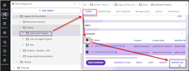
Navigate to the folder that contains IGX files (documents).
-
In that folder select all the IGX files, and/or folders that contain IGX files, with diagrams that you wish to import to web diagram format.
-
Click the ‘IMPORT IGX’ button (at the lower-right of the contents window pane)
-
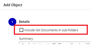
Optional (Recommended): Check the option to include any IGX Documents in sub-folders:
-
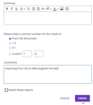
Fill in any other fields of the displayed dialog box, e.g. choose a version for the new file, the comment that will be stored in the history, etc.:
-
Click the FINISH button.
Separate web diagrams of the same name will now be created in the same folder, and if there was more than one diagram in the IGX document, a folder containing diagrams will be created.
Repeat steps 2 to 7 above, as necessary, for all folders with IGX file (document) content. This won’t be necessary if you select the root (top) of the repository tree, select all folders, and use the ‘Include IGX Documents in sub-folders’ option when importing IGX files.
Adjusting the Imported Diagram
There are likely steps you’ll need to take to adjust and/or ‘clean up’ the imported web diagram(s). Again, however, we recommend you read the Appendix entry on possible adjustment to diagrams before importing them as well.
Some possible actions you may need to take after checking out the diagram:
-
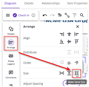
Adjust sizes of shapes, e.g. to fit text, to have shapes cross lanes, or to simply make the diagram look better.
Tip: In the Arrange menu , after selecting a set of shapes, use the ‘Make Same Size’ option to quickly size all shapes to be the same:
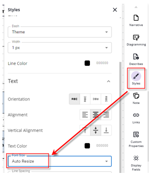
Tip: You may also, or instead, want to adjust the font of the shapes to ‘Auto Resize,’ which will change the size on each shape to fit text into the current size of the shape.
-
Make Lanes bigger to fit shapes.
-
Replace shapes with proper BPMN shapes (if you didn’t do this in the Client, as we recommend; see the Appendix for more details).
-
Make the diagram conform more completely to any current template you may have (e.g., Change formatting on the diagram to match your standards, add a Diagram Name/Title in the Header/Footer area, set colors/theme and fonts, etc.).
-
If you have had a repository already, and have made ‘Describes’ relationships in your IGX diagrams, those Describes Relationships are carried over but are in “proposed state.” To make all these relationships ‘official,’ you must ‘Accept’ them:
a. Check out the web diagram
b. Click View
c. Select Describes List
d. Click ACCEPT ALL
e. Check in
Remember to Check In your changes!
Note: If necessary (e.g., the diagram was Approved), run an Approval Cycle to Approve the latest version you’ve created by editing the diagram content (If necessary, you may use an empty cycle group to make it ‘instantly approved,’ or Bulk Approval Options are available).
Appendix: Important Related Information
If Desired, Adjust the IGX Diagrams BEFORE Conversion to Web Diagram Format
If you want BPMN-format diagrams, which is the ‘default’ format for web diagrams in the Process 360 Live Design platform, you may want to make additional adjustments before import / conversion to web format. Using BPMN format diagrams also makes it easier to use as a ‘conformance’ model for process mining, to deploy the diagram content to automation systems, etc.
The following information outlines methods of making your diagrams more BPMN Compliant, or simply adjusting content in the desktop client before import / conversion:
Making Your Diagrams BPMN Compliant
Ensure 1 Pool on Top of All Lanes
-
Ensure there is 1 top Pool over all other lanes, as BPMN expects a Pool and each Lane will be interpreted as a Pool otherwise. If there is not 1 Pool, use the Swimlane Manager to move the lanes hierarchically:
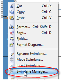
a. Right-click a Lane (Swimlane®) and choose Swimlane Manager:
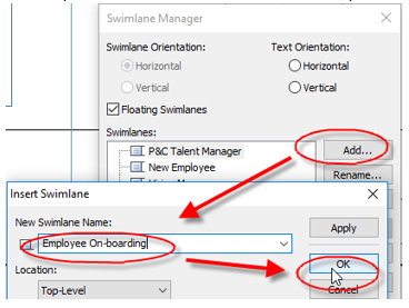
b. Add a top-level lane and name it the same as the process:
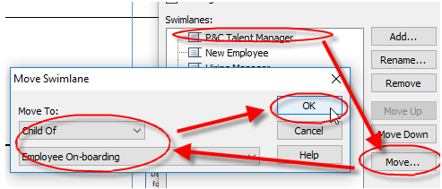
c. Move each of the Swimlanes underneath the Pool (repeat for each Swimlane):
d. Click OK on the ‘Swimlane Manager’ dialog box.
Change the diagram to BPMN format
To change the diagram to BPMN Format:
-
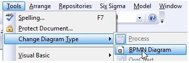
Change to BPMN format: Tools > Change Diagram Type > BPMN
-
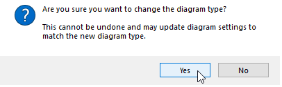
Click Yes to the prompt
Recommended: Clean Up the BPMN-format Diagram
-
Recommended: Clean up the diagram. Depending on how the diagram was created, and your moving of Swimlanes, you may need to clean things up a bit. This may include the following:
a. format painting the new Pool (lane)
b. moving text
c. moving lines off boundaries (right-clicking and choosing ‘Route Line’—if offered—may help)
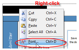
d. Changing to readable fonts (e.g. in the title bar). Note you can right-click and choose font:
Other Possible Clean-Up
The following are some other possibilities, based on experience from many customers' data sets:
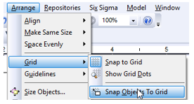
e. Get everything on the placement grid (Ctrl+A, Arrange > Grid > Snap Objects to Grid) and then move around as-needed to make it look nice (you may want to do this earlier, or more than once, depending upon cleanup).
f. Sub-processes may need to be set to ‘Collapsed Subprocess’ activity type and choose (select / tick) the ‘Call Activity’ option box as well… (BPMN Guide page of Properties).
g. The diagram may be offset from the top of the page (to allow room for header information, etc.). You may want to remove this. To do so:
i. Format > Diagram
ii. Click the Process tab
iii. Click Advanced
iv. Change the Offset from Top to 0
v. Click OK.
vi. Click OK again (to save and close the format diagram dialog box).
h. You may need to edit links to other data; use the Properties dialog box Links page to do so.
i. Get rid of spurious / empty text annotations on lines.
j. Start and/or End shapes may not be properly set as Events of Type None; use the Properties dialog box to fix this:
k. Lines may be backwards; use Arrange > Reverse Ends to fix (or delete and re-draw the line. Lines are one-direction in iGrafx, and someone may have formatted a double-arrowhead line that doesn’t come across. Never use a double-headed arrow for sequence flow in a Process diagram).
l. You may need to change regular shapes into ‘Group’ graphical objects. (Drag-drop the ‘Group Artifact’ object from the Shape Palette into the diagram, size & format appropriately (perhaps doing Arrange > Order > Send to Back), delete the existing shape, and then move the group into position).
m. You may need to indicate where Controls (or Risks?) are. This may have been done with formatting that is not kept on export, or even illegal in BPMN (e.g. dashed blue line for shape border). If so, for now a text annotation indicating the control may suffice (use the ‘Capital A’ Text Tool on the Toolbox Toolbar).
n. Make shapes cross-lane (though this may be easier in the Web Diagram).
o. Decisions may not be properly recognized. They may not be Exclusive (X) gateway shapes (e.g. may instead be rounded rectangle ‘Activity’ boxes, ‘Parallel Gateway’ diamonds with the “+” in them); you may need to make them Exclusive Gateway shapes. To do so:
i. Edit the shape Properties (double-click the shape, or right-click and choose Properties)
ii. Go to the BPMN Guide page
iii. If necessary, choose the Gateway for BPMN Flow Object Type
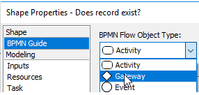
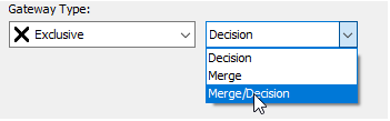
iv. Choose Exclusive and Decision or Merge/Decision Gateway Type (if you are unsure, choose Merge/Decision)
v. Click on the next shape to fix (your changes are automatically applied), or click Apply or OK.
vi. Decision paths may not be (probably are not) recognized; you may need to right-click the lines to get yes / no (and/or edit properties on the Outputs page to choose ‘Other’ for case text and type in custom labels).
vii. You may now need to delete the ‘yes’ and ‘no’ text sitting over the lines for decision cases, if someone did not use the built-in decision behavior of the Desktop Client.
-
Make the diagram BPMN compliant, resolving any warnings or errors. Do a Model > Check, Current Process, OK. Some things you might want (or have) to do:
a. You may need to add ending, or starting, events (Event of type none; the blank circle shape) where needed (Start/End shapes must be used consistently).
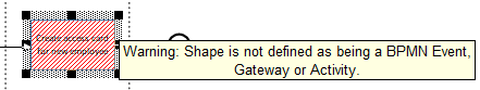
b. Resolve shapes that aren’t seen as BPMN shapes (e.g. by going to the Properties of the shape, BPMN Guide, and changing to the proper BPMN shape):
c. Add gateways to make it clear where there are decisions vs. parallel flow.
Some Important Known Limitations for Importing IGX Documents
The following outlines some known limitations—as of version 19.0—with importing IGX Documents to web diagram format for cloud (or on-premises repository starting with v16). The items are numbered for reference only (are not in any order of importance):
-
Custom Data (including on VSM diagrams): Custom Property Data information is lost. Symptoms of this include:
a. Any Value Stream Map (VSM) data will be lost; Times, defect rates, etc. No timeline will be showing after conversion, and no Timeline data will be kept.
b. Any custom properties in other diagram types (e.g., if you had a custom property called “Pain Point” that contained text, it will not be in the imported / converted web diagram).
-
Simulation Data: Simulation data does not import. You will have to turn the diagram into a simulation project and re-enter all simulation data in order to simulate.
a. Diagram: The diagram will import, and all simulation data in the diagram will be lost.
b. Scenario: Not imported.
c. Report: Not imported.
-
Sheet Data: Any sheet data, including FMEA sheets, will not be imported.
-
Cause-Effect Diagrams: Cause-Effect diagrams may not import cleanly and could need to be edited (for example, lines may not be connected, or it may no longer look like a ‘Fishbone’ diagram).
-
Field data: Some ‘Field’ data may be lost: If the field, including any custom icon, is not defined in the Cloud ‘web diagram’ solution, then that information can be lost.
-
Lines and Text May Not Be 100% the Same: Connection lines and/or Text may look different, be in different locations, be disconnected, or otherwise not 100% match the IGX diagram source.
-
Artifacts (Graphics and Text) May Not Convert 100%:
a. Text Brackets may Move: The location of the square bracket on text in a BPMN diagram may move.
b. Graphic Artifacts may Lose Identity: Artifacts in BPMN diagrams may not convert as corresponding named shapes, and may need to be ‘Changed’ to the appropriate shape.
-
Task Type Indicators: Task types are not allowed on Call Activity shapes, and will be lost.
-
Embedded Files: If you used the ‘Insert OLE Object’ capability, that data will be lost (and if you represent it with an icon, any label will be lost, and the border will likely be invisible).
Suggestions for IGX File Documents After Import
Now that you have imported your IGX files into web diagrams, you will still have your original IGX files (documents) in the repository. Some suggestions of what to do with this content:
-
Archive the IGX File Content (vs. Deleting it):
-
Create a ‘Legacy IGX Content’ or ‘Archived IGX Files’ folder
-
Set permissions on the folder so that only ‘Admins’ can edit, and everyone else can ‘View.' This will allow people to see the legacy data if it is needed.
-
You may want to consider revoking any ‘Approved’ status of the documents once the web diagrams have been approved. This will further ‘hide’ the data from those people that should only see the Approved version of the process / diagram.
-
-
Use the History page of the new diagram to find the archived document, if needed. When importing an IGX Document, the creation comment/entry in the history of the web diagram will have an entry that says something like “Diagram imported from…“ with a link to the original document. As long as that IGX Document still exists in the repository, then it may be viewed from the web diagram’s History page.
-
Hide (or, if necessary, Delete) the IGX Document after an ‘appropriate’ length of time, or some condition, is met. You may have retention policies that must be met. For example, here are some recommendations:
-
When the web diagram is approved, remove the ‘View’ ability for anyone except Admins, or maybe even except for a ‘service account’
-
When a certain length of time is met (e.g., the last modified date of the IGX document exceeds 7 years), delete the document. Remember that you can use the iGrafx Process 360 Live Design reporting functionality to report on all IGX documents that were modified more than a certain number of days (or years) ago.
-